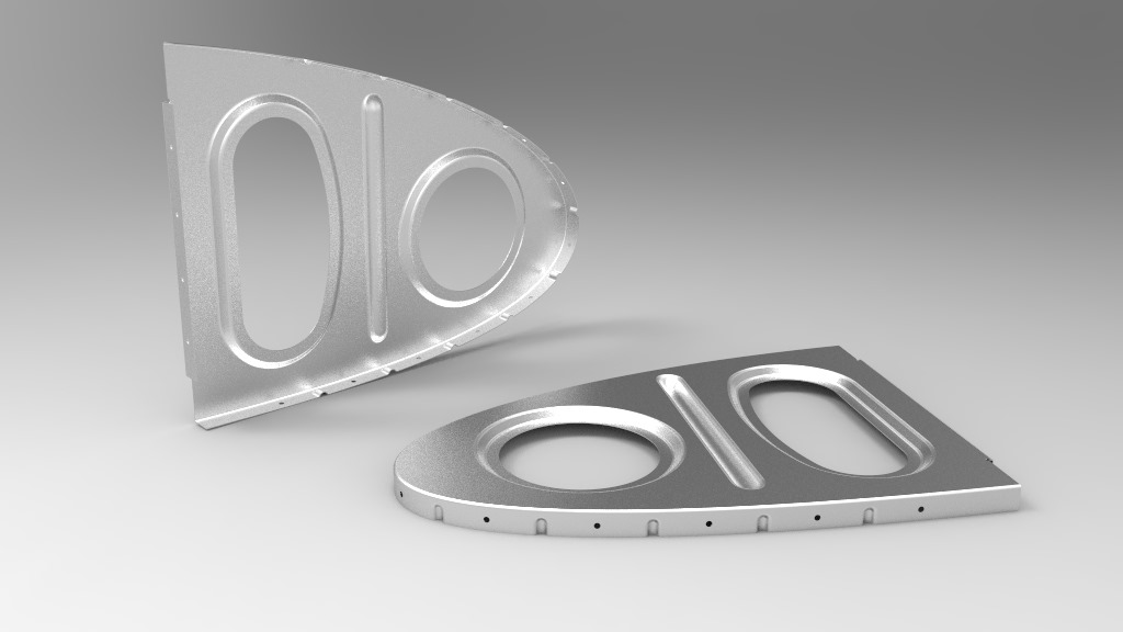
Dans cet article vidéo, voici comment, à l’aide de l’atelier Generative Sheet Metal Design…
Sommaire
Dessiner une nervure d’aile en aluminium emboutie
La vidéo de l’article
Résumé de la vidéo
Dans cette vidéo, je vous montre comment, à partir des courbes d’intrados et d’extrados d’un profil d’aile NACA 4418, faire une première plaque puis:
- Les bords tombés en prenant en compte la position exacte du bord (prise en compte de l’épaisseur de la peau de l’aile).
- Un embouti rond, son placement et la réalisation du trou centré sur cette bosse à un diamètre proportionnel à celui de la bosse.
- Un embouti de type boudin basé sur une ligne.
- Un embouti surfacique avec un trou suivant systématiquement le bord de l’embouti.
- Deux façons de positionner les trous sur les bords tombés.
- Le gaufrage du bord tombé qui n’est pas droit.
- Des perçages dans des zones planes
- Des perçages dans des zones gauches.
Conclusion
Cet article donne une approche de l’atelier Generative Sheet Metal Design pour la conception d’une nervure de bord d’attaque d’un aile d’avion métallique.
Les fonctions abordées sont de toutes façons transposables à d’autres domaines moins aéronautiques.
J’espère que cet article vous a plu. Si vous êtes comme moi passionné d’aviation, cela vous donnera peut être envie de modéliser un début d’aéronef : )
Pensez à partager cet article et à m’encourager en mettant un Like, c’est toujours sympa ; )
.
4 Responses
Hi PSX59,
Hope you’re doing good .. (No idea why you choose this name?? but because it’s weird! it does sound good).
Again an outstanding video of yours, i wander how much views it would make if it were in English!! from my side, you have my full support, so please keep up the good work.
To be honest, the model inside has got my full attention. a NACA 4-digit airfoil is something that tried to model before! and i faced a lot of problems when i did that. so now, i want to share with you some of those along with the hope that you can find time to help me.
link to the files:
https://drive.google.com/open?id=0B_acKm21n7wraTdaQmtXei1jenc
https://drive.google.com/open?id=0B_acKm21n7wrbzc0Uy01X1VKMkk
https://drive.google.com/open?id=0B_acKm21n7wrS25mQ2NJb0xYUTg – please check it.
https://drive.google.com/open?id=0B_acKm21n7wrSmJyYWhQYy0xcDg
Hope to hear from you in the very soon time,
Best wishes for you.
Abdellah
Hi Abdellah,
Thank you very much for your comment and your fosterings.
I’ve just taken a look at your documents.
It’s very interesting.
There are many ways to do that. You took the option to create dynamics upper and lower curves when I choosed to start from an existing table managed by a script.
You know maybe this article about that:
https://apprendre-la-cao.go.yo.fr/comment-crer-un-profil-daile-partir-dun-fichier-de-points-catia-v5-surfacique/
It’s made from Python.
This is the simplest method, I think. I generate a Catpart for each profile I want. To build my wing, I create a link (paste with link) from the profile model and I can replace it by a new one.
I can also position many different profiles along my wings to create an evolutive shape.
There is may be an another way by using a 4 or 5 digits NACA engine associate to a Catia script.
I think about JavaFoil. This is a solution between yours ans mine.
You have made a great works with laws and I think your are close to the end.
I can’t help you because I have’nt enought time for the moment but I think it’s very interesting for me.
I’ll take time to take a look to the Naca 4 digits generation ?
PS:
PSX59 was a code name when I was a glider pilot.
I know that Apprendre-la-CAO should be more efficient on the web in English but I’m not good enough in this language.
Hi PSX59,
Thank you for considering my comment, that really made me happy.
About the modeling i know i choose the hard way to that!? (working with lows to create dynamic curves!!) but after i sow the this men did! IT TURN INTO SOMETHING ELSE FOR ME!!
https://grabcad.com/sbm2-1/projects?page=1 – please check it
i was aware of the other methods used to built the model but a parametric one is still the best!
About Python been used to do the job, honestly i did expect that, i rather was waiting you to suggest VBSripting. since it is supported on CATIA, but you didn’t? i mean is there any reason for that!? VBSript goes well with this kind of work, furthermore it can be applied on SolidWorks as well, so why?
best wishes
Abdellah
Hi Abdellah,
I checked about the Grabcad link.
I thaught I was the only one to work on a propeller blade who come from NACA 640 report.
I also made a post to present my work about it:
https://apprendre-la-cao.go.yo.fr/pale-d-helice-sous-catia-v5-utilisation-des-lois/
Your way to obtain the airfoil is good because it is dynamic but you are constraint to use only Naca 4 digit airfoil (or 5 digits with another one model).
The methode I propose works with all of the airfoils like Clark Y used in the propeller blade.
That’s why I choose to do this. My goal is to draw airplanes and gliders who use different airfoils than NACA.
Look at my project (The site is translated in english):
http://PSX-Aviation.fr
I chose to use Python for sevral reasons:
-It is possible to pilote Catia from the outside of the application.
-It is possible to create a GUI in python and we haven’t interactive dialog boxes in catia Vba.
-Python is for me more accessible and easy than VBa.
-I can mix VBa and python code to pilot Catia (Win32com facilities)
-I had any expérience in Catia/Python software dialog.
I also try to pilot Catia from the outside with VisualBasic.NET Express.
It works perfectly, look at these posts:
https://apprendre-la-cao.go.yo.fr/comment-faire-une-premiere-application-catia-v5-vb-net/
https://apprendre-la-cao.go.yo.fr/catia-v5-creation-de-parametres-via-vb-net/
https://apprendre-la-cao.go.yo.fr/une-application-vb-net-pour-convertir-des-fichiers-catia-v5-aux-formats-standards/
Now I think it is easier and powerful to use VB.Net to script Catia.